X

Partner Login

Enter your username and password here on order to log in on the partner portal:

No registered partner yet?

Register now

China Top 10 Multilayer Flex PCB Manufacturers?

China’s Multilayer Flex Pcb sector serves products where space, weight, and movement all matter. A compact phone camera module, a folding hinge, or a medical probe may rely on thin copper layers and carefully controlled bends. The engineering is exacting. A small error in stack-up or bend radius can create failures that are hard to spot during a quick inspection.

IPC’s 2023 World PCB Production Report put total global PCB production at about US$73.4 billion. That figure covers the wider PCB market, not multilayer flex boards alone, so it should not be mistaken for flex-specific revenue. Still, it shows the scale of the industry in which Chinese suppliers compete. Prismark’s industry research also tracks flexible circuits as a distinct product category, making it a useful reference when comparing market segments. Numbers need context.

For this “China Top 10 Multilayer Flex PCB Manufacturers” guide, rankings should be treated as a starting point—not a substitute for supplier audits. Compare layer-count capability, copper type, minimum bend radius, impedance control, and documented process quality. Ask for cross-sections and test records, not just polished product photos. PCB technologist Happy Holden’s published design-for-manufacturing guidance reinforces a practical point: manufacturability should shape the design early. That is easy to overlook. A supplier may advertise fine-line capability, yet the real question is whether it can repeat that result across production runs. The list ahead aims to help readers ask better questions, while recognizing that public information cannot reveal every factory’s day-to-day consistency.
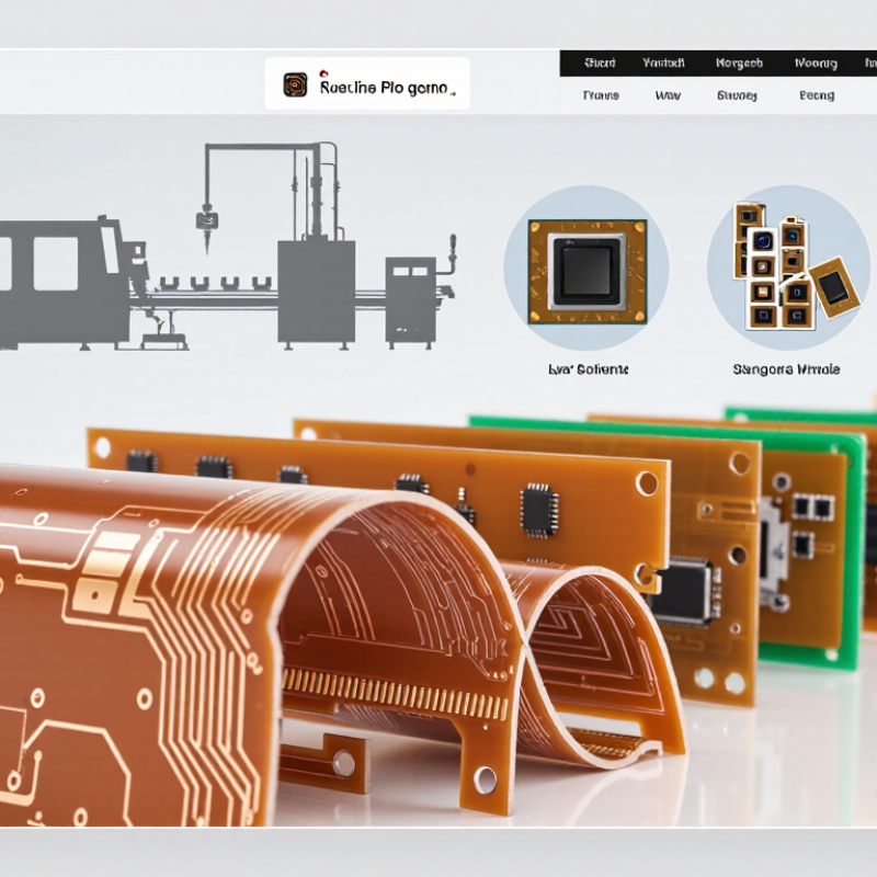
China Top 10 Multilayer Flex PCB Manufacturers?

What Defines a Multilayer Flex PCB? Three or More Conductive Layers

A multilayer flex PCB has three or more conductive layers, separated by flexible dielectric films such as polyimide. Copper layers carry signals, power, and ground; plated vias connect them through the stack. IPC-2223B, the industry design standard for flexible printed boards, treats layer arrangement and bend conditions as core design considerations. The layer count alone does not make a board suitable for repeated motion.

In a practical stack-up, a designer may place a ground plane between signal layers to reduce interference, then add coverlay to protect exposed copper. A connector end might stay flat while a narrow tail bends around a housing. Useful detail. More layers can support denser routing, but they also increase thickness and make bending more demanding. IPC-6013E sets qualification and performance requirements for flexible and rigid-flex printed boards; engineers use such criteria alongside stack-up and bend testing. The exact bend limit depends on construction and motion, so one generic radius is not enough. This is easy to underestimate. A neat layer diagram still needs validation against the device’s real movement.

Which IPC Standards Apply? IPC-6013 and IPC-2223 for Flexible Circuits

For multilayer flexible circuits, IPC-6013 and IPC-2223 serve different purposes. IPC-6013 sets qualification and performance requirements for flexible printed boards, including inspection and acceptance criteria. IPC-2223 addresses design practices for flex circuits, such as bend areas, conductor routing, and transitions between rigid and flexible sections. One defines performance. The other guides design.

Consider a four-layer flex tail folding around a compact enclosure. A sharp crease near a plated via may concentrate stress, while copper crossing a bend can crack after repeated movement. IPC-2223 helps designers evaluate these risks; IPC-6013 helps teams specify and verify the finished board. Neither standard removes the need to review the actual stack-up, bend radius, and use conditions. That part is easy to underestimate.

For a clear supplier specification, state the applicable revisions, board class, flex construction, and acceptance requirements. Check the contract and customer requirements, since the correct revision can vary by project. A standard alone is not a complete drawing. Even careful designs may need adjustment after prototype testing; that is inconvenient, but better than assuming a paper rule predicts every fold.

IPC Standards for Multilayer Flexible Circuits

IPC-2223 provides design guidance for flexible printed boards. IPC-6013 sets qualification and performance requirements, including conformance assessment. This chart shows each standard’s primary role; it does not rate manufacturers or replace review of the applicable revisions and customer requirements.

How to Evaluate Manufacturers: Layer Count, Trace Width, and Production Capacity

For a China-focused multilayer flex PCB shortlist, compare verified process limits, not headline claims. Prismark’s 2024 industry review estimated global PCB production value at about US$69.5 billion in 2023. That scale signals a broad supplier base, but it does not prove any factory can meet your design or delivery schedule. Ask for recent, anonymized production records.

Check layer count against a representative stack-up, including copper weight, coverlay, stiffeners, and finished thickness. A stated maximum layer count is only useful if the supplier has built similar flexible constructions at production volume. For trace width and spacing, request fabrication tolerances and a cross-section or test coupon from a comparable job. IPC design guidance helps frame requirements, but your actual limits depend on material, copper, and process control. Tiny traces need evidence.

Capacity needs equally careful checking. Ask for monthly good panels, typical yield, current utilization, and lead times for both prototypes and repeat orders. A large equipment list can hide bottlenecks in lamination, drilling, or inspection. Prismark’s market data is useful context, not factory-level proof. Numbers need context. I would also ask what happens when a yield target is missed; suppliers do not always answer that clearly. Compare the same panel size and build complexity across candidates.

China’s Top 10 Multilayer Flex PCB Manufacturers: Profiles and Capabilities

A credible profile of China’s ten leading multilayer flex PCB manufacturers should compare engineering depth, not just factory size. Look for demonstrated experience with multilayer stack-ups, fine-line circuitry, controlled impedance, copper balancing, and stiffener integration. Ask how each supplier handles bend-radius limits and repeated-flex testing. These details affect whether a circuit survives installation or cracks near a connector. Details matter.

Capability claims need context. Request sample cross-sections, inspection criteria, and yield data for a comparable design. Check whether the supplier can document materials, process changes, and electrical test results. IPC-6013 provides qualification and performance requirements for flexible printed boards, giving buyers a common reference point. A profile should also distinguish static-flex products from dynamic-flex designs; they do not face the same fatigue demands.

Market data explains why supplier comparisons require care. Prismark’s 2024 industry review put worldwide PCB production at roughly US$73 billion in 2023, following a cyclical downturn. That figure covers the broader PCB sector, not multilayer flex alone. It signals a large, changing market, but cannot verify any individual factory’s capability. One weakness in many shortlists is that they rank suppliers without publishing comparable test conditions. Treat rankings as a starting point, then verify performance using your own stack-up, bend cycle, and acceptance criteria.

China’s Top 10 Multilayer Flex PCB Manufacturers: Profiles and Capabilities

Anonymous capability profiles for comparison—not a verified company ranking. The figures below are representative ranges and process examples found across flex PCB manufacturing; actual limits depend on material, stack-up, panel size, and qualification requirements. Confirm current capabilities directly with each supplier.

Profile Typical Product Focus Multilayer Construction Representative Line / Space Materials and Copper Fabrication and Assembly Best-Fit Applications
Profile 1 — High-volume consumer flex Thin, lightweight flex circuits for compact electronic assemblies. Commonly 2–6 conductive layers; rigid-flex options may be available. About 75–100 µm line / space for many production designs. Polyimide base films; rolled-annealed or electrodeposited copper, commonly around 12–35 µm. Coverlay, stiffeners, surface finishes, electrical testing, and volume panel production. Wearables, mobile accessories, cameras, and compact consumer devices.
Profile 2 — Fine-feature flex specialist High-density routing and small-pitch interconnects. Often 2–8 layers, subject to stack-up and yield requirements. Approximately 50–75 µm line / space on suitable designs. Thin polyimide and copper foils selected to meet routing and bend requirements. Fine imaging, laser drilling for suitable features, controlled impedance, and microsection inspection. Display connections, camera modules, compact sensors, and miniaturized electronics.
Profile 3 — Multilayer rigid-flex producer Integrated rigid and flexible sections in one interconnected assembly. Combined rigid-flex stack-ups commonly range from 4 to 12 or more total layers. Typically 75–125 µm line / space; capability varies by rigid-flex transition design. Polyimide flex layers with rigid-section materials and bonding systems matched to the stack-up. Sequential lamination, plated interconnections, coverlay, stiffeners, and rigid-flex testing. Medical equipment, industrial controls, aerospace electronics, and space-constrained assemblies.
Profile 4 — Dynamic-flex applications Circuits intended to flex repeatedly during normal operation. Usually simpler, thinner flex stack-ups; multilayer designs require careful mechanical review. Often designed around 75–125 µm line / space rather than maximum density. Flexible polyimide and rolled-annealed copper are commonly considered for repeated bending. Bend-zone design review, strain relief, controlled coverlay openings, and sample-cycle evaluation. Moving print heads, folding mechanisms, robotic joints, and repeatedly actuated assemblies.
Profile 5 — High-layer-count flex producer Complex routing for dense interconnect and demanding system layouts. Some suppliers offer 8–12 or more flex layers, depending on material and design rules. Common production designs may use 75–125 µm line / space; denser features require qualification. Polyimide-based constructions with copper thickness chosen for current, routing, and flexibility needs. Multilayer lamination, plated through-holes, impedance control, and stack-up engineering. Instrumentation, communications equipment, and complex industrial electronics.
Profile 6 — Automotive flex supplier Flex and rigid-flex circuits for qualified vehicle electronics programs. Typically project-specific multilayer flex or rigid-flex constructions. Often 75–150 µm line / space for production designs, with tighter rules subject to approval. Materials and finishes selected for the operating environment and customer specifications. Traceability, process controls, electrical testing, and quality documentation may be required by program. Lighting, displays, sensors, control modules, and other vehicle subassemblies.
Profile 7 — Medical and reliability-focused producer Controlled-process flex circuits for equipment with demanding reliability needs. Layer count and stack-up tailored to electrical, mechanical, and qualification requirements. Typically 75–125 µm line / space for many designs. Documented material selections, including polyimide systems, based on customer requirements. Inspection records, lot traceability, electrical test, and support for customer qualification plans. Diagnostic equipment, monitoring systems, imaging devices, and medical instruments.
Profile 8 — RF and controlled-impedance flex Flex circuits designed for signal integrity and high-frequency performance. Often 2–6 layers, with reference-plane and ground structures defined in the stack-up. Commonly 75–125 µm line / space, adjusted for impedance and material properties. Low-loss or specialized flexible materials may be evaluated alongside standard polyimide. Impedance modeling, controlled stack-up, coupon testing, and connector-launch review. Antennas, radio modules, high-speed links, and communications equipment.
Profile 9 — Heavy-copper and power flex producer Flexible circuits carrying higher current or distributing power. Typically 1–6 layers, with conductor geometry and thermal conditions central to design. Often 100–200 µm line / space; wider conductors may be used for current handling. Copper thickness may range from about 18 to 70 µm or more in specialized constructions. Current-capacity review, thermal assessment, robust pads, and connector or terminal integration. Battery connections, power modules, lighting, and industrial equipment.
Profile 10 — Prototype-to-production flex partner Engineering support and production scaling across a broad range of flex designs. Commonly 1–8 layers, with rigid-flex or higher-layer-count work subject to project review. About 75–150 µm line / space for many designs; advanced features require a DFM check. Standard polyimide and copper options, with stack-up recommendations for cost and performance. Design-for-manufacturing feedback, prototypes, electrical testing, and repeat-order support. New product development, industrial devices, electronics startups, and low-to-medium volume programs.

Where Are Multilayer Flex PCBs Used? Automotive, Medical, and Electronics Applications

Multilayer flex PCBs help connect components where space is tight and wiring must bend around moving parts. In automotive systems, they may route signals through steering columns, instrument panels, door modules, or compact sensor assemblies. A thin flex section can reduce bulky wire bundles and simplify assembly. It still needs careful protection from vibration, heat, and repeated movement.

Medical equipment uses flexible circuits in devices such as endoscopes, wearable monitors, and portable diagnostic tools. Their narrow profiles can fit inside curved housings, while multiple conductive layers support power and signal routing in limited space. Cleanability and dependable electrical performance matter. A design that bends easily on a bench may not survive repeated use or sterilization conditions, so testing must reflect the real device.

Consumer electronics also rely on multilayer flex circuits in cameras, foldable displays, and compact handheld products. Designers use them to connect boards across hinges or around small enclosures. The trade-off is real: more layers can improve routing density, but they may increase cost and make bending less forgiving. Bend radius, copper placement, shielding, and connector strain deserve attention early. Flexibility is not magic. Some layouts look elegant in a drawing yet prove difficult to assemble, and that is worth questioning before production.