X

Partner Login

Enter your username and password here on order to log in on the partner portal:

No registered partner yet?

Register now

What Is a Hydraulic Piling Rig and How Does It Work

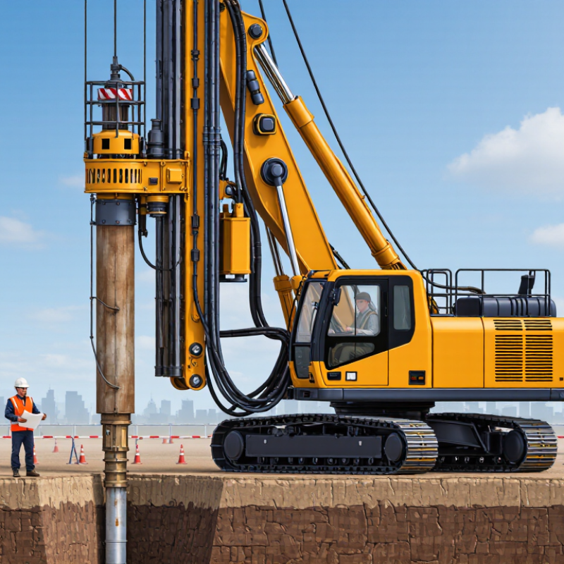
A Hydraulic Piling Rig is a machine that installs foundation piles using hydraulically powered equipment. It may press, rotate, drill, or drive piles, depending on its attachments and the ground conditions. A power pack sends pressurized fluid through hoses to motors and cylinders. These components move the mast, turn the drilling tool, or operate the pile clamp. On site, the process is visible: the leader stands upright, the operator aligns a pile, and the rig applies controlled force.

Geotechnical engineer Dr. Donald A. Bruce’s work emphasizes matching construction methods to ground conditions. A practical paraphrase of that principle is: “Let the ground conditions guide the installation method.” This is a paraphrase, not a verbatim quotation. It captures an important point. A rig’s performance depends on more than engine power. Soil layers, groundwater, pile type, and access all matter. A pile may advance smoothly through loose soil, then slow sharply at dense material. That change deserves attention, not guesswork.

This guide explains the main rig components and how hydraulic power becomes movement and force. It also looks at common installation methods, site checks, and operating limits. Not every machine works the same way. That distinction matters. A drilling attachment and a pressing system solve different problems, even when they share a chassis. Understanding the difference helps readers assess equipment claims and ask better questions. The machinery can look straightforward. The ground rarely is.
What Is a Hydraulic Piling Rig and How Does It Work

Definition and Core Function of a Hydraulic Piling Rig

A hydraulic piling rig is a foundation machine that uses pressurized oil to move and control its working equipment. Pumps supply hydraulic flow to motors and cylinders, which can raise the mast, rotate drilling tools, apply downward force, or extract them. The exact setup depends on the attachment. Some rigs drill pile locations; others install piles with a separate hydraulic hammer. Terminology is not perfectly consistent. The label alone can be misleading.

Its core function is to transfer controlled force and motion into the ground while keeping the tool aligned. On site, an operator may adjust rotation and feed as a drill enters changing soil layers; the rig’s hydraulic system helps manage that movement. Measurements matter. FHWA’s 2016 report, Design and Construction of Driven Pile Foundations (GEC 12), describes dynamic pile monitoring using force and acceleration measurements near the pile head. These readings help assess driving resistance and stresses during installation. They are not a substitute for sound site investigation or engineering judgment. Soil conditions can change within a short distance, and machine settings that work at one pile may need revision at the next.

Main Components and Their Roles

A hydraulic piling rig installs piles by applying controlled force through a mast-mounted tool. Its carrier, often fitted with tracks, supports the machine and helps it move across the work area. The mast, or leader, guides the pile and keeps the driving equipment aligned. A small misalignment can affect the pile’s position.

The hydraulic power pack supplies pressurized fluid to pumps, valves, cylinders, and motors. Cylinders raise or tilt the mast, while hydraulic motors may operate a rotary drive or assist a piling hammer. A winch can lift piles and attachments; guides help steady the pile during setup. The operator uses controls to adjust movement and pressure, while gauges provide useful feedback. Pressure matters. The layout is not always as tidy as a diagram suggests, so hose condition and clear movement paths deserve attention.

Tips: Check hydraulic hoses, fittings, and fluid levels before work. Confirm the mast is set for the pile and ground conditions. Small details count. Stop and reassess if the rig moves unexpectedly or the pile begins to lean.

How Hydraulic Power Drives the Piling Process

Ahydraulic piling rig uses pressurized oil to turn engine power into controlled movement. An engine drives pumps, which send fluid through hoses to cylinders and hydraulic motors. These components raise the leader, position the pile, and power a hammer, vibratory unit, or press-in mechanism. The exact setup depends on the rig and ground conditions. Small movements matter.

When the operator selects a function, valves direct oil to the required circuit. Pressure creates force in a cylinder, while flow rate affects how quickly it moves. During driving, the attachment transfers impact, vibration, or steady pushing force to the pile. Sensors and gauges help the operator monitor pressure, alignment, and temperature. A warm hose or drifting pile can signal a problem.

Hydraulic power allows force and speed to be adjusted during the cycle. An operator might move slowly while setting a pile, then increase output once it is stable. But the controls cannot make every soil layer predictable. Dense gravel, buried debris, or changing water conditions may alter resistance from one metre to the next. Good practice means checking the pile’s position and machine readings, not trusting sound alone. I would treat those readings as clues, not certainty.

Step-by-Step Pile Installation Workflow

Step-by-Step Pile Installation Workflow

Work begins with reviewing the ground investigation, pile layout, and design requirements. The crew checks access, working-platform stability, and underground-service information before setting up. These checks are easy to rush. They should not be. The rig is positioned over the marked pile location, then leveled so the leader guides the pile vertically. A surveyor may confirm the position and alignment before installation.

The crew lifts the pile into the leader using approved lifting points and secures it in the rig’s guides. Depending on the design and ground conditions, the pile is driven with a hydraulic hammer or pressed into the soil. Some projects use predrilling where specified. During installation, operators watch pile verticality, penetration rate, hydraulic pressure, and any unusual movement or noise. Readings are recorded at intervals, not just at the end. Real sites rarely behave exactly like drawings.

When the pile reaches its specified depth or installation criteria, the crew checks its final position and records the result. If a pile needs an extension, the joint is prepared and connected according to the project procedure before work continues. The pile is then cut to the required level, and inspection or testing follows the project plan. A pressure reading alone does not prove capacity; ground response and verified records matter too.

What Is a Hydraulic Piling Rig and How Does It Work - Step-by-Step Pile Installation Workflow

Step Workflow Stage What Happens Rig or System Involved Typical Checks and Records
1 Understand the rig A hydraulic piling rig uses a diesel engine or electric motor to drive hydraulic pumps. Pressurized fluid powers functions such as moving the mast, operating the winch, positioning the pile, and running a compatible piling attachment. Power unit, hydraulic pumps, control system, mast, winch, and piling attachment Confirm the rig and attachment are suitable for the pile type, required capacity, ground conditions, and project method statement.
2 Review the design and prepare the site Review pile locations, design details, ground information, access requirements, and the approved installation method. Prepare a stable working platform and identify underground or overhead hazards. Rig working platform, site survey information, and safety controls Verify platform condition and bearing capacity against project requirements; confirm service locations, exclusion zones, and access routes.
3 Set out the pile position Surveyors mark the designed pile location and establish any required reference points before the rig is positioned. Survey instruments, pile-position markers, and rig positioning system Record the pile reference and confirm the marked position against the approved setting-out information.
4 Position and level the rig The operator moves the rig over the pile location, stabilizes it as required, and aligns the mast to the specified orientation and inclination. Crawler chassis or carrier, hydraulic mast controls, and leveling indicators Check rig stability, mast alignment, working clearances, and that the attachment is correctly connected and inspected.
5 Lift and align the pile The pile is lifted using approved lifting points and gear, then positioned beneath the hammer or other installation attachment. The pile is aligned with the set-out point. Service winch or crane, certified lifting accessories, pile helmet, and guides where required Inspect lifting gear, confirm the pile identification and condition, and verify line, level, and safe control of the suspended load.
6 Start pile penetration For a driven pile, a compatible hydraulic impact hammer applies repeated blows through a pile helmet or cap. The pile advances into the ground as the hammer transfers energy to it. Hydraulic impact hammer, hoses, power unit, helmet, and pile guides Follow the approved hammer settings and installation sequence; watch for pile damage, abnormal movement, leakage, or unsafe vibration.
7 Monitor driving progress Driving continues in a controlled manner while the pile’s position and penetration are monitored. Splices, if needed, are completed using the specified connection method before driving resumes. Hammer controls, survey equipment, and pile-driving monitoring instruments where specified Record penetration and driving data required by the project; check alignment and inspect pile joints and exposed pile sections.
8 Reach the specified acceptance criteria Installation stops when the project’s approved criteria are met, such as the specified depth, set, or other defined requirement. Refusal should be treated according to the project procedure, not assumed to mean acceptance. Hydraulic hammer and project-specified monitoring or survey equipment Compare installation records with the design and specification. Refer unexpected refusal, damage, or deviations to the responsible engineer.
9 Complete records and move to the next pile After installation, the pile is identified and its as-built position and installation details are recorded. The rig is repositioned for the next pile following the approved sequence. Installation log, survey equipment, and rig travel and positioning systems Record pile ID, location, installed length or depth, relevant driving data, observations, and any approved corrective action.
10 Carry out specified verification Testing or inspection is performed when required by the design or specification. The method may include integrity testing, static load testing, or other project-approved checks. Test equipment selected for the specified verification method Confirm test results are reviewed and accepted by the responsible engineer before the pile is relied upon for the next construction stage.

Scope note: This workflow describes a typical hydraulic impact-hammer method for installing driven piles. Hydraulic piling rigs can also be configured for other methods, and the exact sequence, equipment, monitoring, and acceptance criteria depend on the pile system, ground conditions, design, and project specification.

Common Rig Types and Construction Applications

A hydraulic piling rig installs deep foundations by applying controlled force through a mast-mounted tool. Hydraulic pumps power the crowd system, rotary head, or hammer, depending on the rig design. The operator positions the tool, advances it into the ground, and monitors pressure, depth, and alignment. Small changes matter. A few degrees of mast tilt can affect pile position.

Common rig types include rotary bored-pile rigs, hydraulic impact hammer rigs, and static press-in rigs. Rotary rigs drill a shaft for a reinforced concrete pile, often used beneath buildings and bridge supports. Impact rigs drive precast concrete or steel piles into the soil, making them useful for waterfront works and retaining walls. Press-in rigs push piles into the ground with hydraulic force and little vibration, which can suit dense urban sites. Each method has limits; hard layers, groundwater, and restricted access can change the choice.

Tips: Check soil investigation data before selecting a rig. Confirm working clearance, ground-bearing capacity, and nearby structures. Track pile depth and verticality during installation, not only at the end. Keep records of hydraulic pressure and interruptions. Readings help, but site conditions can still surprise the crew.

Typical Pile Diameter Ranges by Hydraulic Rig Type

Representative diameter ranges; actual capabilities vary with rig configuration, tooling, and ground conditions.

Rotary bored rigs are used for large-diameter foundations, while continuous flight auger rigs suit cast-in-place piles in suitable soils. Driven piling rigs install precast piles by impact or vibration; micropile rigs drill smaller-diameter elements for restricted-access or ground-improvement work. Ranges overlap and are indicative, not design limits.