X

Partner Login

Enter your username and password here on order to log in on the partner portal:

No registered partner yet?

Register now

How to Choose Threaded Inserts in 2026?

Choosing Threaded Inserts in 2026 means matching the insert to the material, load, and installation conditions—not simply picking a thread size. A metal insert in a plastic housing faces different risks from one installed in wood or a thin sheet. A mismatch can lead to stripped threads, rotation, or a joint that loosens under vibration. Small details matter.

“[Insert a verified, source-checked quotation about insert selection],” says [verified expert name and professional title]. This quotation should come from a named specialist or manufacturer source, with its wording and attribution confirmed before publication. Expertise is useful only when readers can check it.

This guide explains how to compare insert types, base materials, thread sizes, and installation methods. It also covers practical checks: expected pull-out force, installation torque, temperature, corrosion exposure, and available tool access. A benchtop test can reveal problems that a catalog table may not show. Still, test results depend on the actual material and installation process.

There is no universal best insert. A choice that works in a rigid aluminum panel may fail in soft plastic. Start with the joint’s real conditions, then confirm the manufacturer’s specifications and test a representative assembly. That extra check takes time. It can prevent a costly redesign.
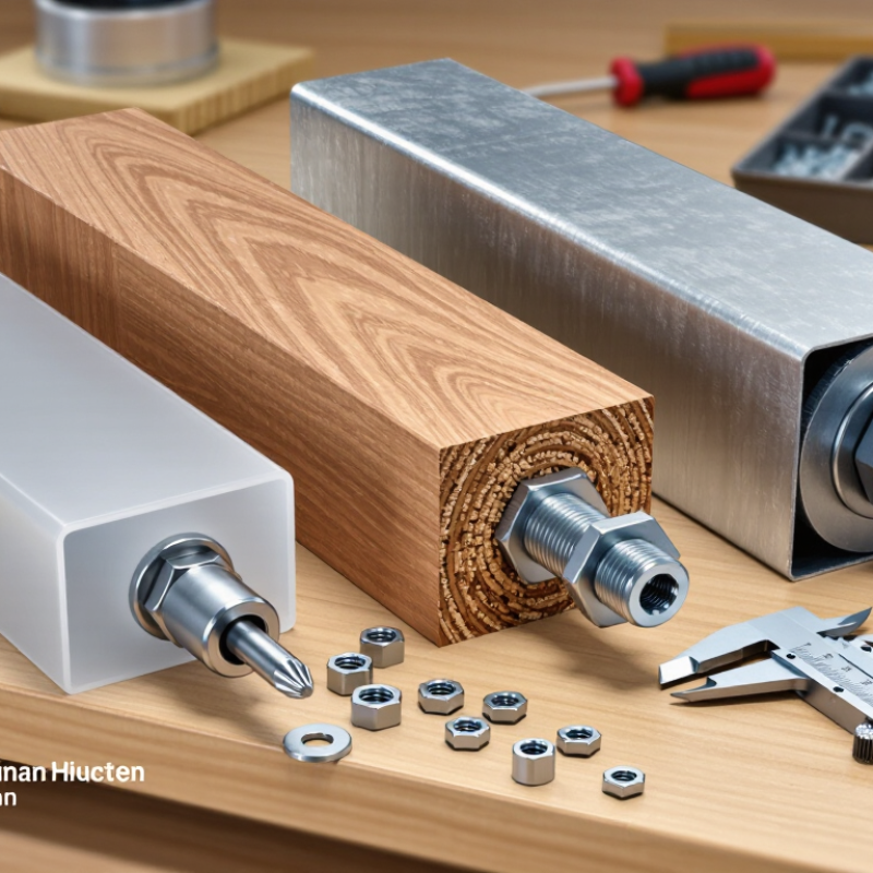
How to Choose Threaded Inserts in 2026?

Classify the Substrate, Load Direction, and Failure Risk Before Selection

How to Choose Threaded Inserts in 2026?

A sound choice starts with the substrate, not the insert catalog. Start with what surrounds the threads. Thin-wall aluminum can deform around an oversized insert, while softwood may split near an edge. Plastics bring another concern: heat during installation can soften the hole. For glass-filled composites, check whether drilling exposes fibers or encourages cracking.

Next, identify the load direction and the likely failure. Axial pull can strip internal threads or pull the insert from the material. Side loads may bend the fastener and loosen its seating. Repeated vibration can cause rotation, while sustained force in plastic may lead to gradual creep. These are different risks. A larger insert may help with pullout, but it will not automatically solve edge breakout or wall collapse.

Match the insert’s geometry and installation method to the material thickness, available clearance, and expected service load. Leave enough distance from edges, and check the maker’s installation data rather than relying on appearance. A small sample panel can reveal trouble early. Test pullout and rotation using the actual substrate and installation tool. A clean bench test is useful, but imperfect; real parts vary, and that variation deserves attention.

Choose ISO 261 Thread Pitches: M6×1.0, M8×1.25, and M10×1.5

How to Choose Threaded Inserts in 2026?
Choose ISO 261 Thread Pitches: M6×1.0, M8×1.25, and M10×1.5

For many metric applications, these three coarse pitches are practical starting points. ISO 261 specifies the preferred thread series: M6×1.0 advances 1.0 mm per turn, M8×1.25 advances 1.25 mm, and M10×1.5 advances 1.5 mm. That spacing matters when matching an insert to a bolt already specified in a drawing or parts list. Check the full designation, not just the “M” size. A fine-pitch bolt will not correctly match a coarse-pitch insert. Small mismatch, real trouble.

Pitch alone does not tell you whether an insert will hold in wood, plastic, or metal. NASA’s Fastener Design Manual, NASA RP-1228, discusses fastener performance in relation to the joint and its loading, rather than thread size alone. In practice, check the base material, available wall thickness, installation method, and expected load before choosing an insert. For example, a thin panel may split or deform even when the bolt pitch is correct. Confirm the insert’s internal thread against the bolt specification, then test installation and retention in representative material. I have seen the pitch get all the attention; the substrate deserves just as much. ISO 261 defines thread dimensions, not the pull-out strength of a particular insert.

Compare Wire, Solid, Press-In, and Heat-Set Inserts by Installation Method

How to Choose Threaded Inserts in 2026?
Compare Wire, Solid, Press-In, and Heat-Set Inserts by Installation Method

The right insert depends on the base material, expected load, and available installation tools. Wire inserts fit a prepared hole cut with a special tap. An installation tool winds the coil into place; some designs require tang removal afterward. They can restore or reinforce threads, but setup takes care. Solid inserts have a rigid body and may screw into a tapped hole or press into a prepared bore, depending on their design. Check the specified hole size and engagement depth before installation.

Press-in inserts rely on an interference fit, often using knurls or ribs to resist rotation in softer materials. A small arbor press can help keep the insert square. Heat-set inserts are commonly used in thermoplastics: a heated tip softens the surrounding plastic, allowing the insert to settle into place. Too much heat or pressure can distort the part. I’ve seen a neat-looking installation still fail when the hole was undersized.

Tips: Test the insert on a sample part first. Keep it aligned, and follow the maker’s temperature and hole-size guidance. Inspect for cracking, tilt, or looseness before assembly. Small details matter.

How to Choose Threaded Inserts in 2026? Compare Wire, Solid, Press-In, and Heat-Set Inserts by Installation Method

Comparison Point Wire Thread Inserts Solid Thread Inserts Press-In Inserts Heat-Set Inserts
How It Is Installed A coiled wire is screwed into a tapped hole using an installation tool. The parent material is tapped for the insert’s specified STI thread. A one-piece metal insert is screwed into a prepared hole. Depending on the design, it may be retained by an interference fit, locking feature, or adhesive. The insert is pushed into a prepared hole, typically with a hand press or arbor press. Knurls, ribs, or other external features grip the surrounding material. A metal insert is placed in a molded or drilled thermoplastic hole and heated with a controlled-temperature tip. The softened plastic flows around its external features and solidifies.
Typical Parent Materials Metals such as aluminum, magnesium, and steel; also used in some plastics when the hole and installation method are designed for it. Metals and some plastics, selected according to insert geometry, material compatibility, and the required retention method. Commonly used in thermoplastics and some sheet or plate materials. The correct insert style depends on material hardness and thickness. Thermoplastics, including many injection-molded parts. Not generally suitable for thermosetting plastics, which do not soften and flow again when heated.
Hole Preparation Requires a correctly sized drilled hole, STI tap, and clean threads. Hole size and tap details must follow the insert specification. Requires a prepared hole and, for screw-in styles, a matching internal thread. Some designs need a counterbore or other specified feature. Requires a hole matched to the insert’s outside diameter and retention features. Hole size, edge distance, and material thickness affect fit. Requires a hole matched to the insert and the plastic part. Molded holes are common; drilled holes should be clean and dimensionally controlled.
Typical Installation Equipment STI tap, wire-insert installation tool, and a drill; a tang break-off tool may be needed for tang-style inserts. Appropriate drill and tap or other specified hole-preparation tools, plus an insert driver or installation tool suited to the design. Hand press or arbor press with an appropriate locating fixture. Controlled pressing helps keep the insert square to the hole. Temperature-controlled insertion tool with a correctly sized tip; production setups may use fixtures or automated insertion equipment.
Main Advantages Can provide durable internal threads in relatively soft metals, help repair damaged threads, and offer a range of standard thread sizes. Provides a robust, self-contained threaded component and can be useful where a wire insert is not suited to the application. Fast installation without a separate heating step; suitable designs can provide useful thread strength in relatively thin sections. Creates a strong threaded attachment in thermoplastics and can accommodate designs where screws will be installed and removed repeatedly.
Key Limitations Installation depends on correct STI threading and tool use. Tang-style versions may require tang removal and inspection. May require more material or a larger installation feature than a wire insert. Retention and removal behavior vary by design. Fit can be sensitive to hole size, material condition, and part thickness. Excessive installation force can crack or distort a part. Requires heat and controlled installation. Excessive heat or force can damage the part; cycle time and access to the hole may constrain assembly.
Best Fit When You need to reinforce or repair internal threads in a metal component and can prepare the hole with the specified STI tooling. You need a solid metal insert and can provide the hole geometry and retention method specified for the selected design. You need a quick mechanical installation and the part material, thickness, and hole geometry support a reliable press fit. You are adding reusable machine threads to a thermoplastic part and can control insert alignment, temperature, and installation depth.
Selection Checks Confirm thread size and pitch, parent-material condition, insert length, installation depth, and whether tang removal is required. Confirm insert style, thread size, hole preparation, retention method, available wall thickness, and service loads. Confirm insert dimensions, recommended hole size, material hardness, part thickness, edge distance, and required pull-out or torque performance. Confirm plastic type, insert dimensions, hole design, tool temperature and tip, installation depth, and the manufacturer’s process guidance.

Note: Performance depends on insert design, parent material, hole quality, installation procedure, and applied loads. Use the selected insert’s technical data and installation instructions to confirm dimensions and process settings.

Match Insert Material and Coating to Corrosion, Temperature, and Wear

Start with the conditions around the insert, not a favorite material. In a damp enclosure or near salt spray, corrosion can attack both the insert and the surrounding part. Stainless steel may suit many wet environments, but “stainless” is not a universal corrosion guarantee. Check the specific grade and consider contact with the parent material. Dissimilar metals can create galvanic corrosion when moisture bridges them. Small detail. Big consequence.

Temperature changes the choice. Heat can reduce the strength of some materials or degrade protective finishes, while repeated heating and cooling may loosen a joint. Check the insert maker’s stated service range for the exact material and coating. Zinc coatings can protect steel in suitable conditions, but they are not ideal for every hot or chemically exposed application. A coating chart is only a starting point, not a final answer.

Wear matters where screws are removed often or vibration keeps stressing the threads. A harder insert may resist thread damage, yet hardness alone does not ensure a durable assembly. Look at the screw material, installation method, and load direction too. For a frequently serviced panel, test a sample by installing and removing the screw several times, then inspect for debris, coating loss, or damaged threads. I would recheck the choice after testing; real assemblies can behave differently from a tidy specification sheet.

Validate Fit and Pull-Out Strength; Use ASTM D7332 for Composite Pull-Through

A threaded insert can feel secure during installation and still pull through a composite panel under load. Check the insert’s grip range against the measured panel thickness, including coatings and local reinforcement. Then test the actual laminate, hole diameter, washer or flange, and installation torque. Small changes matter. A countersink, crushed edge, or uneven seating can shift the failure from thread damage to laminate pull-through.

ASTM D7332/D7332M-16(2021), Standard Test Method for Measuring the Fastener Pull-Through Resistance of a Fiber-Reinforced Polymer Matrix Composite, provides procedures for measuring pull-through resistance. Record peak load, displacement, specimen thickness, and failure mode; do not report load alone. Compare results across enough specimens to see scatter, not just the strongest sample. CMH-17, Volume 3, presents statistically based design data for polymer-matrix composites, but those allowables are material- and configuration-specific. They are not universal insert ratings. That distinction is easy to miss. A useful qualification report should identify the laminate layup, conditioning, fixture, and fastener geometry alongside the measured values. If the insert will see cyclic or wet-service loading, a single room-temperature pull-through test may leave an uncomfortable gap in the evidence.

How to Choose Threaded Inserts in 2026?

Validate fit and pull-out strength; use ASTM D7332 for composite pull-through.

The chart shows nominal coarse-thread pitches, not insert pull-out ratings. Confirm the insert’s specified hole size, material thickness, and installation requirements. For fiber-reinforced polymer composites, ASTM D7332 provides a method for measuring fastener pull-through resistance; test representative coupons and compare results with your design load.