How to Choose the Right Radial Lead Capacitor
Choosing the right radial lead capacitor can affect far more than whether it fits the circuit board. Capacitance, rated voltage, temperature range, and ripple-current capability all shape how reliably it performs. The term Lead Radial Capacitor describes its lead arrangement, not its internal construction. That distinction matters. A radial electrolytic part and a radial film part may look similar in a catalog, yet serve very different circuit needs.
Start with the circuit’s operating conditions and the manufacturer’s datasheet. Check the required capacitance and allow sensible voltage margin, while avoiding assumptions that a higher rating always means a better choice. For power-supply filtering, compare ripple-current ratings and equivalent series resistance where relevant. For timing or signal paths, leakage, tolerance, and dielectric behavior may deserve closer attention. Then measure the available footprint. A capacitor that clears the schematic but touches a heatsink is not a good fit. Small detail, big consequence.
Temperature and service life also count. A warm enclosure can shorten the useful life of some electrolytic capacitors, so compare lifetime ratings at the stated temperature. Confirm polarity before installation, and verify lead spacing against the board. These checks are practical, but not infallible; real operating conditions can differ from bench estimates. A little uncertainty is worth admitting. This guide explains how to weigh the key specifications, compare suitable options, and avoid choices based only on price or appearance.
Understanding the Construction and Function of Radial Lead Capacitors
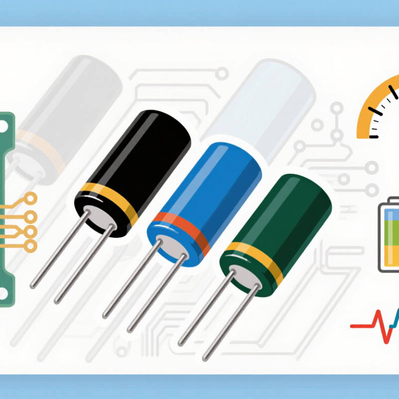
A radial lead capacitor has both wire leads extending from one end of its body. This layout fits many through-hole circuit boards, where the leads pass through drilled pads and are soldered underneath. Inside, conductive plates or foils are separated by a dielectric material. The exact construction depends on the capacitor type: an electrolytic design may use a wound element and electrolyte, while a film design uses thin plastic layers. The outer sleeve protects the component and often carries its key ratings.
Its job is to store and release electrical charge. In a power supply, it may smooth voltage changes; in a signal circuit, it can help block direct current while passing changing signals. The role depends on the circuit, not just the shape. That detail matters. A radial body does not tell you whether the part is polarized, or how it will behave at high frequency.
When choosing one, compare capacitance, rated voltage, temperature range, and physical dimensions with the circuit and board layout. Check lead spacing too; a few millimeters can make assembly awkward. For ripple-heavy power circuits, review ripple-current and equivalent-series-resistance ratings in the datasheet. Small parts still vary. It is easy to focus on capacitance alone, but that can miss heat, space, or lifetime concerns. A quick fit check on the board is useful, though it cannot replace checking the electrical ratings.
Identifying the Circuit’s Capacitance and Voltage Requirements
Before choosing a radial lead capacitor, identify the capacitance the circuit actually needs. Check the schematic, component specifications, or a reliable circuit calculation rather than guessing from the old part alone. In a timing circuit, capacitance affects the interval; in a filter, it influences ripple and response. Load, signal frequency, and operating temperature can also matter. A quick measurement can help, but an in-circuit reading may be misleading.
Tips: Record the required capacitance, tolerance, and operating conditions. Compare the part’s datasheet with the circuit’s needs. Keep notes; small details are easy to miss.
Next, determine the highest voltage the capacitor will experience, including realistic startup peaks or transients. Choose a rated voltage above that level, and follow the manufacturer’s derating guidance for the specific capacitor type. More voltage margin can improve reliability, but it does not replace checking temperature, ripple current, or polarity. For polarized capacitors, confirm the positive and negative connections before installation. I have seen voltage estimates based only on the normal reading; that can overlook brief surges. Check the actual circuit conditions, and revisit your assumptions if measurements disagree.
Comparing Tolerance, Temperature Range, and Electrical Performance
Choosing the right radial lead capacitor means matching its specifications to the circuit, not just its printed capacitance. Tolerance shows how far the actual value may vary. A 10 µF part with ±20% tolerance may measure between 8 and 12 µF. That difference can affect timing, filtering, or signal response. Tight tolerance is useful when the circuit depends on a predictable value. For general smoothing, a wider tolerance may be acceptable.
Temperature range matters when the capacitor sits near a warm power component or in an unheated enclosure. Check the operating limits and capacitance change across that range. Then compare rated voltage, ripple current, and equivalent series resistance (ESR) with the circuit’s demands. A capacitor can meet its voltage rating and still run hot under ripple current. It is easy to overlook that detail. Also confirm lead spacing and body size before fitting it to a board.
Tips: Read the full datasheet, not only the value printed on the sleeve. Compare specifications at the expected temperature and operating frequency. Leave sensible voltage margin, and check ripple current against the circuit load. If the circuit behavior is uncertain, measure it under realistic conditions. That extra check may catch a mismatch before assembly.
Checking Lead Spacing, Dimensions, and Mounting Compatibility
A radial capacitor can fit its holes and still sit badly. Measure lead pitch from centre to centre, not from the outside edges. Common through-hole pitches include 2.5, 5.0, and 7.5 mm, but verify the exact drawing for each part. A small mismatch can pull leads sideways, tilt the body, or stress the seal. Measure twice. I still find this easy to overlook when comparing parts by capacitance alone.
Check body diameter, height, and lead length against the board layout and nearby components. Leave room for the capacitor body, solder fillets, and any tool used during assembly. IPC-2221B, Table 6-1, gives conductor-clearance values by voltage category; lead pitch itself does not establish safe electrical clearance. For dimensions and mounting, use the capacitor’s mechanical drawing and the PCB footprint together. IEC 60384-1 provides a framework for fixed-capacitor specifications, but the relevant detail specification supplies the part-specific limits. One imperfect check is measuring a sample against the board before ordering a large quantity. It catches awkward fit, though it cannot replace the drawing.
Verifying Safety Ratings and Operating Conditions
A radial lead capacitor can look suitable on paper and still be unsafe in its actual circuit. Check the datasheet’s rated voltage, temperature range, ripple-current limit, and intended application. A DC voltage rating does not establish suitability for an AC line position. If the part connects across line and neutral, or from line to earth, verify its safety class and approval markings for that exact position. Do not infer these from appearance.
The markings matter.
Then compare real operating conditions with the specified limits. A warm enclosure, frequent voltage spikes, or heavy ripple can shorten service life. Allow for the manufacturer’s derating guidance, and check the capacitor’s maximum temperature and expected lifetime at the measured temperature.
For polarized electrolytic types, confirm polarity and ripple limits; for any type, ensure the lead spacing and body fit the board without strain. Keep clearances appropriate to the circuit.
A quick visual check is not enough.
I would recheck the datasheet against the actual circuit, especially when a design runs near its limits. That step is easy to skip. It is also easy to regret.


 Distributors
 SDS Download
 Contact
