Partner Login
Enter your username and password here on order to log in on the partner portal:
No registered partner yet?
Register nowChoosing a China-based manufacturer for an Illuminated Tact Switch means looking beyond a bright sample and a competitive quote. The switch must feel consistent, fit the panel, and remain readable in its intended lighting. A careful review starts with practical details: actuator height, operating force, mounting dimensions, LED color, and terminal layout. Ask how the supplier checks these features across production batches. Details matter.
Experienced buyers also examine samples under real conditions. Test the switch in the actual enclosure, with the planned light pipe or panel opening. A button that looks clear on a workbench may appear dim or uneven behind tinted plastic. Confirm the expected operating life and environmental conditions with documented specifications, rather than relying on broad claims. Request drawings, test records, and clear answers about customization and quality checks. These steps help separate capable manufacturers from listings that offer little technical detail.
China’s supplier base includes companies with different strengths, from standard catalog parts to customized assemblies. Compare their engineering support, communication, sample process, and ability to keep specifications stable. Not every option fits. One point deserves reflection: the lowest unit price can hide extra development time, inconsistent illumination, or a long approval process. Reliable sourcing is less about finding a perfect promise and more about verifying what the manufacturer can repeat. With measured testing and clear requirements, buyers can shortlist suppliers more confidently and select an Illuminated Tact Switch suited to the product, not merely the quotation.
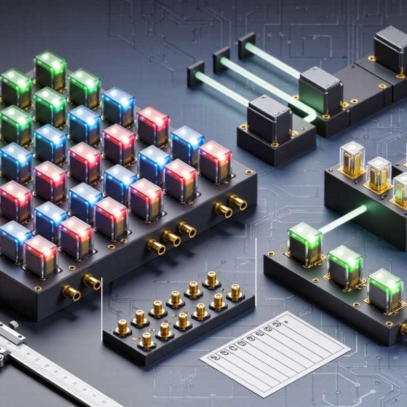
An illuminated tact switch combines a momentary mechanical switch with a small light source, usually an LED. Pressing its cap moves a spring-loaded contact, briefly closing an electrical circuit. Release the cap, and the contact opens again. The LED may turn on with the circuit, or operate separately through another pin. That depends on the design. Visibility matters. In a dim control panel, a colored cap can help an operator find the right button without changing position. Clear wiring diagrams and pin labels are essential because the light and switch circuits may be independent.
Brightness, color, operating voltage, and mounting dimensions all affect selection. The U.S. Department of Energy’s LED Lighting guidance reports that LEDs can use up to 90% less energy and last up to 25 times longer than incandescent lighting. Those figures describe LEDs generally, not the lifetime of a complete tact switch. One caveat. Heat, frequent pressing, soldering conditions, and panel exposure can affect actual performance. A common design mistake is treating brightness as the only goal; a very bright indicator may cause glare, while a dim one can disappear under strong ambient light. Check the switch’s datasheet for measured electrical and mechanical ratings, then test the assembled panel in its real lighting conditions.
China Best Illuminated Tact Switch Manufacturers
An illuminated tact switch combines a spring contact, actuator, housing, terminals, and light source. The contact dome creates the familiar click and returns the actuator after release. An LED may sit beside the contact, or a light guide may spread its output beneath a translucent cap. That small optical path matters. Uneven brightness can make a symbol look washed out, especially in a dark control panel.
Grand View Research estimated the global LED lighting market at USD 75.6 billion in 2023, with a projected 10.8% compound annual growth rate from 2024 to 2030. This broader lighting trend is not a tact-switch sales forecast, but it shows why compact illuminated controls attract design attention. For component selection, compare operating force, travel, contact rating, LED voltage, and mounting method. Also check light uniformity on the actual PCB; drawings can hide shadows from nearby parts. A common design miss is specifying a bright LED before checking heat and current limits. Bright is not always better.
For robustness, review the intended ESD environment and test conditions. IEC 61000-4-2:2008 includes test levels up to 8 kV contact discharge and 15 kV air discharge. These are test levels, not automatic product guarantees. Dust, soldering heat, and repeated actuation can also affect performance. Prototype the switch in its final enclosure. A clear lens may still distort color.
LED color is a key design choice for an illuminated tact switch. The chart shows representative nominal forward voltages; actual values vary with the LED and operating current. Check the component datasheet when selecting a switch or designing its drive circuit.
China’s illuminated tact switches are built through several tightly controlled production steps. Manufacturers typically mount LEDs and other components onto circuit boards, then combine them with molded housings, metal contact domes, and button caps. Automated optical inspection can flag shifted components, solder defects, or inconsistent LED placement. Operators also check samples by hand; tiny parts can still escape detection.
Testing covers both switching action and illumination. Equipment measures operating force, travel, contact resistance, and LED current, while cycling rigs repeatedly press sample switches to assess wear. For electrostatic-discharge planning, IEC 61000-4-2:2008 defines test levels up to 8 kV for contact discharge and 15 kV for air discharge. These are system-level test benchmarks, not proof that every switch receives those tests. Buyers should request the manufacturer’s actual test plan and results. Small details matter.
A capable factory records batch numbers and links test results to production lots, making failures easier to trace. Yet test fixtures can differ, and a passing sample cannot guarantee identical performance across every shipment. That limitation deserves attention. Ask how suppliers control LED brightness and color variation, and whether they test switches under the intended board and operating conditions. A switch may click reliably on a bench but feel different after installation.
When evaluating China’s illuminated tact switch manufacturers, start with the switch’s job, not a catalogue photo. Confirm the actuator size, mounting footprint, travel, and operating force against the panel design. Ask how the LED is driven and whether its color and brightness stay consistent across production lots. A bright sample is useful, but it cannot tell the whole story.
Request dimensional drawings, material details, rated electrical limits, and test records for endurance and contact performance. Check whether the supplier can explain the test setup, sample quantity, and acceptance criteria. These details make comparisons more meaningful than a single lifetime figure. Small details matter. Inspect samples for uneven light bleed, loose terminals, or a button that sticks after repeated presses. If something feels slightly off, request another sample; it may slow the decision, but guessing carries its own risk.
Manufacturing control deserves equal attention. Ask how incoming LEDs and contact parts are checked, how changes are documented, and whether dimensions remain stable between batches. Review packaging and lead-time assumptions, especially for delicate surface-mounted parts. A low quotation may still be suitable when specifications and inspection plans are clear. I would not treat a polished brochure as proof of reliability. Compare written evidence, sample behavior, and communication, then choose a manufacturer whose answers stay specific when requirements become less convenient.
| Evaluation Criterion | What to Check | Evidence to Request | Practical Evaluation Guide |
|---|---|---|---|
| Electrical Ratings | Rated voltage and current, contact configuration, and the specified resistive or other load conditions. | Current datasheet, product drawings, and test conditions for the exact part number. | Compare the ratings with the application. Do not assume a rating applies to every load type or operating condition. |
| Illumination Performance | LED color, forward voltage, forward current, polarity, brightness data, and illumination uniformity where specified. | LED specifications, circuit guidance, and sample measurements or visual samples at the intended operating conditions. | Confirm that LED drive requirements match the design and that the illuminated legend or window is suitable for the intended environment. |
| Operating Life | Electrical and mechanical life, plus the load, actuation force, travel, and test method used for each figure. | Datasheet life ratings and test reports identifying conditions and acceptance criteria. | Compare like-for-like test conditions. A cycle-life figure without its conditions is not sufficient for a direct comparison. |
| Mechanical Fit | Body dimensions, mounting method, terminal layout, actuator height, operating force, and total travel. | Dimensioned drawings, tolerances, recommended PCB footprint, and physical samples. | Check the switch against the enclosure, PCB, and actuator stack-up; verify fit with a sample before design freeze. |
| Environmental Protection | Operating temperature range and any stated dust or water protection rating. | Datasheet limits and, where an IP rating is claimed, supporting test documentation referencing the applicable IEC 60529 classification. | Treat protection as model-specific. Do not infer an IP rating from appearance or from another product in the range. |
| Materials and Compliance | Declared material composition and the product’s status against applicable substance restrictions and market requirements. | Product-specific compliance declarations and supporting material documentation; confirm scope and revision dates. | Verify documentation for the exact model and target market. A general company statement may not establish product-level compliance. |
| Quality Management | Documented production controls, inspection procedures, nonconformance handling, and traceability. | Quality-system certificate, its validity and scope, sample inspection records, and an explanation of lot identification. | Check that certificates cover the relevant manufacturing site and activities; assess production controls separately from certification. |
| Customization and Engineering | Available options for cap, illumination, actuator, terminals, packaging, and application-specific requirements. | Written feasibility review, revised drawings, prototype plan, and confirmation of design-change control. | Evaluate the supplier’s ability to document and validate changes, not only its willingness to offer customization. |
| Supply and Communication | Quoted lead time, minimum order quantity, sample availability, capacity information, and response to technical questions. | Written quotation, sample schedule, production and shipment assumptions, and a named point of contact. | Treat lead times and order quantities as quote-specific. Confirm them for the required configuration and order volume. |
| Sample and Production Validation | Consistency between approved samples and production parts, including function, dimensions, illumination, and packaging. | Pre-production samples, agreed inspection criteria, and a change-notification process for materials or manufacturing. | Approve samples against documented requirements and define how future production lots will be checked. |
Suggested scoring: Rate each criterion from 1 to 5 based on the completeness and verifiability of the evidence provided. This framework is for supplier comparison; specifications and commercial terms must be confirmed for each model and quotation.
Illuminated tact switches are useful wherever an operator needs clear, immediate feedback. They appear on appliance control panels, access equipment, instruments, and compact industrial interfaces. A lit key can help users find a control in a dim room or confirm that a setting has changed. Keep the light purposeful. Excessive brightness can cause glare, especially on glossy panel surfaces. A small prototype can reveal this problem before tooling begins.
Selection starts with the electrical and mechanical requirements. Match the LED’s rated voltage and current to the circuit, and check whether the switch offers the required color and viewing angle. Then compare actuation force, travel, and expected operating life with how often the key will be pressed. Panel thickness, mounting method, and available board space matter too. For dusty or damp locations, verify the specified protection level; a sealed panel does not automatically make the switch itself resistant. Test samples under the actual lighting and temperature conditions when possible. Check soldering compatibility as well. Specifications can look neat on paper, but tactile feel and visibility may differ in a finished enclosure. That detail is easy to overlook.