Partner Login
Enter your username and password here on order to log in on the partner portal:
No registered partner yet?
Register nowIn 2026, the best Flexible Feeding System is the one that handles your actual parts reliably, not the one with the flashiest brochure. Imagine a bowl of mixed components, a camera locating each piece, and a robot waiting for a consistent pickup. Small changes in shape, surface, or orientation can disrupt that sequence. So can a system that is difficult to clean or reset.
The International Federation of Robotics’ World Robotics 2024 report recorded 541,302 industrial robot installations worldwide in 2023. That figure describes the broader automation market, not flexible feeding alone, but it shows why dependable part presentation matters. Marina Bill, then president of the IFR, described the wider trend: “The global robotics market is on a growth path.” For buyers, growth is not a specification. Fit is.
A useful comparison should examine part range, changeover time, singulation performance, footprint, and integration with existing robots and controls. Ask suppliers for trials using your own parts, including the awkward ones. Request measured cycle times and recovery data, not just demonstration footage. Still, no system wins everywhere. A compact feeder may suit tiny precision components, while larger or delicate parts may need a different approach. This is where buyers can misjudge the choice: impressive speed means little if misfeeds keep stopping the line. The right system depends on the parts, the required output, and the people maintaining it.
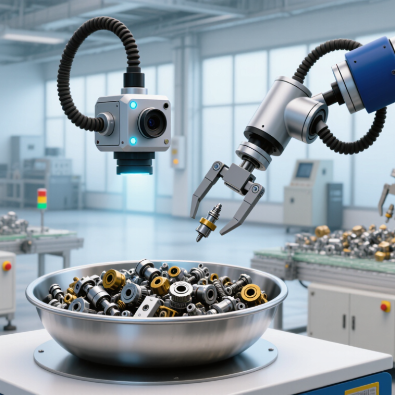
A flexible feeding system is equipment that presents loose parts to a machine in a controlled, repeatable way. Unlike a dedicated feeder built for one part shape, it can often handle several product types with fewer mechanical changes. A typical setup includes a hopper, a spreading surface, a camera or sensor, and a robot or transfer mechanism. The system separates parts, identifies their position and orientation, then guides them toward the next operation. That matters. When a part changes, an operator may adjust software settings or a fixture instead of rebuilding the entire feed path. Not magic.
In practice, flexibility depends on the parts and the required production rate. A vision-guided system may work well with small components that arrive in mixed orientations, while heavy or tangled parts may need different handling. For example, parts spread across a vibrating tray can be inspected and picked one at a time. Operators still need to check for overlap, glare, dust, and inconsistent surface finishes. These details can affect detection. A flexible feeder can reduce changeover effort, but it may cost more and require careful setup. It is not always the best fit. Before selecting one, test actual parts at realistic speeds, and record where the system struggles. That honest trial often reveals more than a polished demonstration.
A flexible feeding system moves loose components from bulk storage to a machine or robot in a controlled flow. A hopper holds parts, while a feeder spreads them across a tray or track. Gentle vibration or programmed movement separates overlapping pieces. A camera then identifies each part’s position and orientation.
The controller links the camera, feeder, and robot. It selects a usable part, sends its coordinates to the robot, and adjusts the feed when the viewing area is empty. That matters. A poorly tuned vibration can make parts pile up instead of separate. In real production, the first settings rarely work perfectly; small changes to feed speed or amplitude can make a noticeable difference.
Changeovers depend on the parts and the system’s capabilities. Operators may load a stored recipe, adjust the tray motion, and verify camera recognition with sample parts. Different finishes, shapes, or surface reflections can affect detection, so testing actual production parts is essential. The setup is not magic. A system that handles one component smoothly may struggle with a similar part that has a narrow edge or tends to nest. Careful trials reveal those limits before the line runs at full speed.
A typical flexible feeding workflow, from bulk part loading to downstream placement.
Parts are loaded in bulk, spread or singulated on the feeder, located by a vision system, picked by a robot, and transferred to the next operation. The bars show workflow order only—not cycle time, throughput, or system performance.
Flexible feeding systems in 2026 range from simple mechanical feeders to vision-guided robotic cells. Vibratory bowl feeders orient small, uniform parts through vibration and shaped tracks. They work well for screws, caps, and other repeatable components. Step feeders lift parts gently, making them useful when noise or surface damage is a concern. Belt and centrifugal feeders offer other ways to move parts, depending on their size, shape, and required speed.
For mixed or delicate components, flexible feeders typically spread parts across a flat tray. A camera identifies suitable positions, and a robot picks parts individually. This approach can reduce the need for custom tooling when product changes are frequent. It still needs careful setup. Reflective surfaces, tangled parts, or poor lighting can confuse vision systems. Small adjustments matter.
The right type depends on the parts and the production task. Check part dimensions, material, surface finish, changeover frequency, and target throughput before choosing. Ask for trials using real parts, not only sample images or ideal conditions. Watch how the system handles a scratched component or an awkward orientation. That test may reveal more than a polished demonstration. No feeder fits every job. Even a flexible system may need new recipes, grippers, or tray settings when parts change.
Comparing flexible feeding systems starts with the parts, not the brochure. List the components you run, including their dimensions, materials, surface finishes, and weekly volume. A system that handles small plastic caps may struggle with oily metal clips. Ask for trials using your actual parts, including awkward shapes and out-of-spec samples. Watch for jams, scratches, and inconsistent orientation. Count them.
Then compare usable output, changeover time, and the space needed around the equipment. A fast cycle rate means little if operators spend ten minutes clearing a tangled batch. Check how recipes are stored and whether adjustments require specialist support. Ask what happens when part quality varies between suppliers. It will. Review guarding, access for cleaning, noise, and how the feeder connects to downstream equipment. Request measured results from a representative production run, not just a short demonstration. Include maintenance, spare parts, training, and energy use when estimating total cost. A lower purchase price can hide recurring labor costs. Still, the neatest comparison spreadsheet can miss real operator habits. Leave room for feedback after a pilot, and revise your criteria when the floor reveals something you overlooked.
The best flexible feeding system in 2026 depends on your animals, feed, and daily routine. Start by recording how much feed each group needs and how often staff refill or inspect equipment. Note whether you handle pellets, grain, mixed rations, or several feed types. Measure twice. A system that moves one feed smoothly may struggle with another.
Next, compare capacity, adjustability, cleaning access, and compatibility with your building. Check whether feed lines, bins, and dispensers can be expanded or repositioned without major work. Ask suppliers for documented throughput, maintenance requirements, and performance under conditions similar to yours. If possible, observe a full feeding cycle and inspect hard-to-reach areas where residue could collect. Small details matter.
Automation can save time, but it should not make problems harder to spot. Look for clear alerts, simple manual controls, and a reliable way to check feed delivery. Consider who will clean and maintain the system, and whether replacement parts are readily available. A paper layout may look convincing; real workflows often expose awkward turns or blocked access. I would test the proposed setup against a busy day, not just an average one. Then compare the total cost of ownership, including installation, energy, labor, and routine servicing.
The best system depends on the parts being handled, required output, changeover frequency, and available floor space. This comparison covers common automated and manual options for presenting components to assembly or inspection equipment.
| Feeding system | How it works | Part variation it can handle | Changeover flexibility | Typical strengths | Considerations | Best suited to |
|---|---|---|---|---|---|---|
| Flexible feeder with vision guidance | A feeder spreads parts on a surface; a camera identifies suitable parts and provides pickup coordinates to a robot. | Often suited to mixed, randomly oriented parts within the feeder, camera, and robot’s operating limits. | High when recipes, vision tools, and robot programs can be changed digitally. | Can reduce the need for a dedicated mechanical track for every part type; supports part picking from a spread-out presentation. | Performance depends on part visibility, surface properties, camera setup, robot reach, and how well parts separate. | Production involving multiple part types or frequent product changes. |
| Vibratory bowl feeder | Vibration moves parts along a bowl track, where tooling guides them into a consistent orientation. | Usually designed around a specific part family and a defined orientation. | Low to moderate; changing parts may require track or tooling adjustments, or a separate bowl. | Can provide continuous, oriented part supply for established, repeatable production. | Custom tooling can make frequent product changes costly; noise, part wear, and track jams should be considered. | High-volume applications with stable part designs and orientation requirements. |
| Centrifugal feeder | A rotating disk moves parts outward toward a discharge area, where guides and controls help orient them. | Works with suitable parts that can be separated and guided reliably; compatibility is application-specific. | Moderate; adjustments or dedicated guides may be needed for different parts. | Can deliver parts at high rates in a compact footprint for suitable applications. | Part shape, surface, and orientation requirements affect performance; parts must be tested with the intended setup. | Consistent production where a suitable part can be separated and oriented at speed. |
| Step feeder | Moving steps lift parts from a bulk supply and transfer them to a downstream track or conveyor. | Best for parts that can be lifted and transferred without excessive entanglement or damage. | Low to moderate; part-specific guides or transfer tooling may be required. | Provides a controlled feed and can be gentler than some bulk-feeding methods. | May require custom tooling and careful assessment of part geometry and orientation needs. | Applications needing a steady supply of parts that are difficult to handle in a vibratory bowl. |
| Linear vibratory track feeder | A vibrating track advances parts from an upstream supply toward a machine or pick point. | Typically handles a defined part type or family presented in a consistent way. | Low to moderate; track width, guides, and controls may need adjustment for a new part. | Useful for buffering and transporting already oriented parts between process steps. | It generally transports parts rather than solving complex orientation needs on its own. | Linking a feeder, assembly station, or inspection process. |
| Manual kitting or tray presentation | An operator places parts into trays or kits in a known arrangement for manual or automated pickup. | Can accommodate a wide variety of parts if the trays and work instructions are suitable. | High; a new layout or work instruction can often be introduced without rebuilding a feeder. | Simple to adapt for prototypes, low volumes, and frequently changing product mixes. | Requires operator time and consistent loading; labor, ergonomics, and presentation accuracy matter. | Low-volume production, pilot runs, or applications where automation tooling is not justified. |
Selection tip: Test representative parts, including the most difficult variants, before choosing a system. Compare reliable part presentation, changeover effort, integration needs, maintenance, and total operating cost—not speed alone. Actual throughput and part compatibility depend on the complete application.